
The Role of Catenary Equations in Sag and Tension Calculations
Derivation of the catenary equation from first principles — sag, maximum sag, and conductor length formulas for overhead transmission line design, explained step by step.
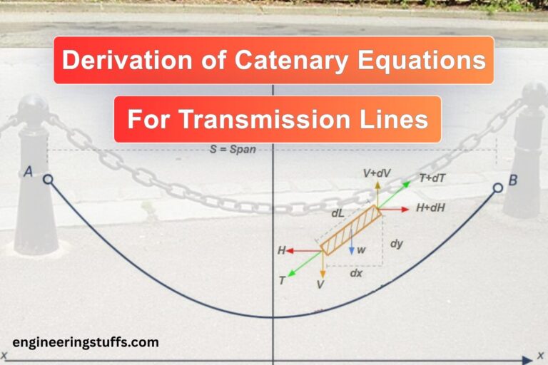
Derivation of the catenary equation from first principles — sag, maximum sag, and conductor length formulas for overhead transmission line design, explained step by step.
A hand-worked bisection iteration for sag-tension calculation, including ice, wind, and NESC k-constant loading, replicable in Excel.
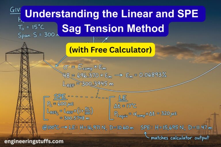
In this post I cover the other two: the Linear Elongation (LE) model and the Simplified Plastic Elongation (SPE) model. Both are simpler and faster than EPE, and both are still widely used in practice — especially for preliminary design or where conductor polynomial data are not available.

We rely on software like PLS-CADD for transmission line design, but understanding the underlying math makes you a better engineer. In this post, we break down the exact hyperbolic catenary equations and 4th-order stress-strain polynomials used in the Experimental Plastic Elongation (EPE) method. Follow a step-by-step hand calculation for a Drake ACSR conductor under NESC extreme loading, and see exactly how the fundamental math compares to industry-standard software outputs.

How do engineers calculate sag and tension in overhead power lines? This article breaks down the key formulas, including the catenary curve and conductor length, and explains how factors like weather and temperature affect these calculations.